What is a Universal Testing Machine?
Universal Testing Machine (UTM) is a highly versatile tool used to determine materials' mechanical properties. The UTM is capable of performing various tests, including tensile strength (how much force a material can withstand when being stretched), compressive strength (how much force a material can endure when being compressed), bending strength, shear strength, torsion, flexural testing, and hardness testing. Its primary function is to apply a controlled force to a test specimen and measure the material’s response, thereby providing valuable data about the material's quality, durability, and safety.
The "universal" aspect of the machine signifies its ability to handle a wide range of materials, from metals and polymers to ceramics and composites, as well as conduct multiple types of tests. It provides key data points like ultimate tensile strength, yield strength, elongation, and modulus of elasticity — all of which are fundamental to understanding how a material will perform under stress in real-world applications.
The machine is designed to follow rigorous standards set by organizations such as ASTM and ISO, guaranteeing consistency and accuracy in testing. Historically, UTMs were referred to as tensometers due to their use in tensile testing, but today, they perform up to 37 different tests, including peel tests, friction tests, and spring tests, making them a cornerstone in both research and development and quality control.
Key Components of a Universal Testing Machine
To understand how a universal testing machine operates, we first need to become familiar with its key components. The main components are as follows:
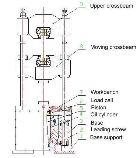
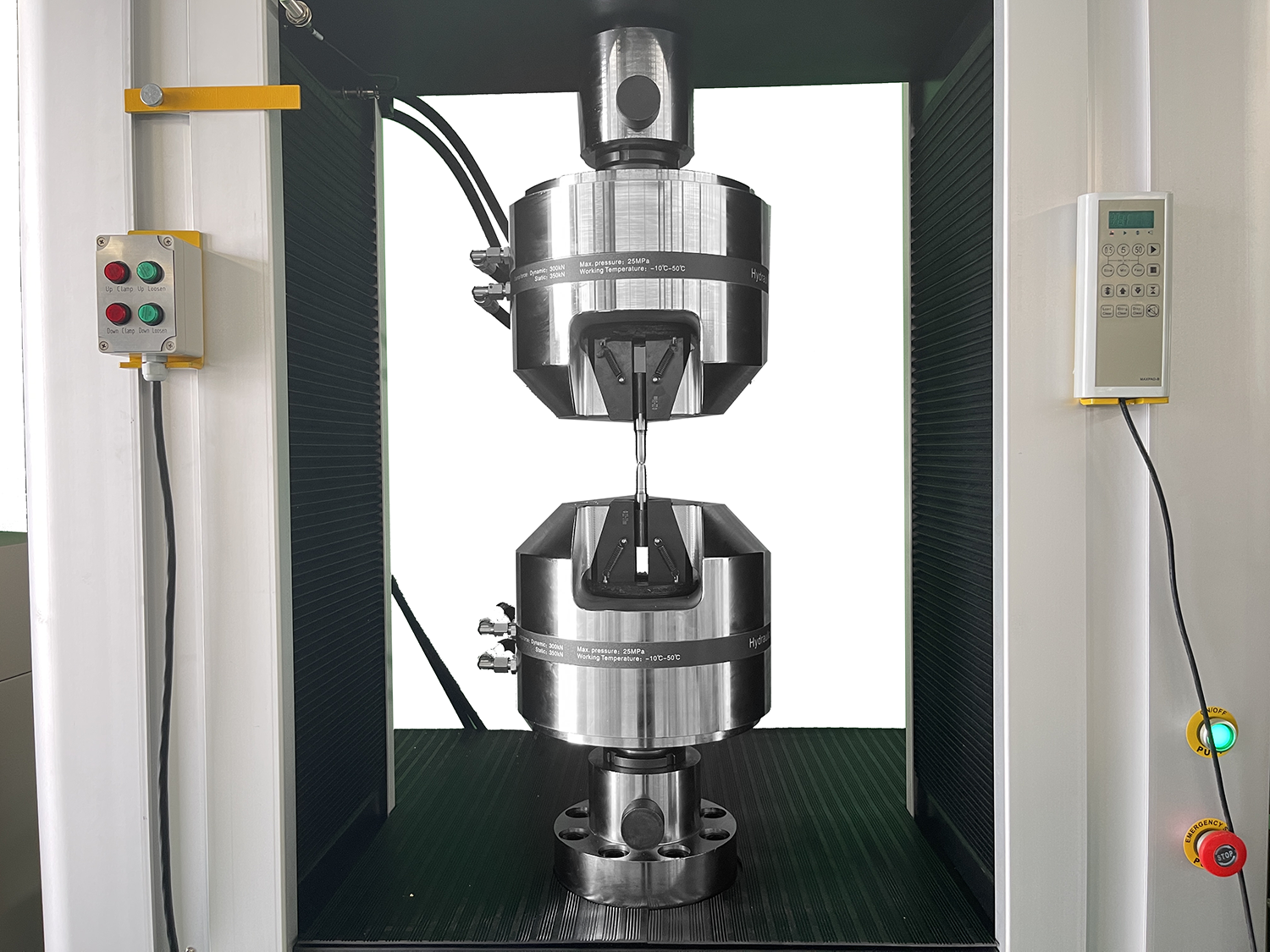
1. Load Frame
The load frame provides the UTM's structural backbone. It houses all the moving parts and provides machine stability during testing. It is typically made from robust materials like steel or aluminum to withstand high forces during tests. The frame holds the crossheads, which move to apply stress to the test specimen.
2. Crosshead
The upper crosshead is usually stationary and houses the actuator and load cell, while the lower crosshead is movable and is responsible for adjusting the height and clamping the test specimen. The crosshead movement applies force to the specimen during testing, whether performing a tensile (pulling) or compressive (pushing) test. Precision moving these crossheads results in accurate and repeatable results.
3. Actuator
The actuator is the UTM's driving mechanism. It controls the crossheads' movement, applying controlled forces to the material. Depending on the machine, the actuator can be hydraulic, pneumatic, or electromechanical. Hydraulic actuators, for example, are known for their ability to generate high forces, making them suitable for heavy-duty applications.
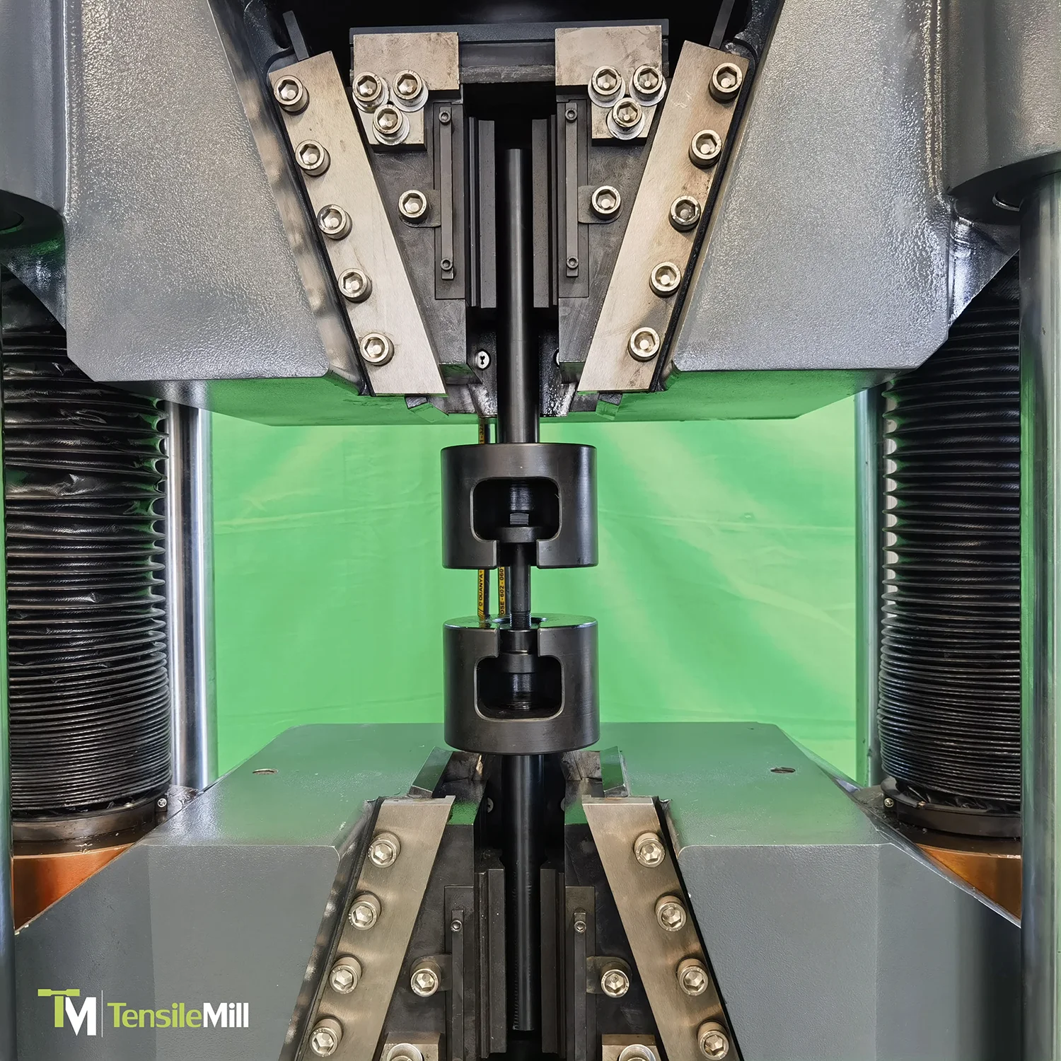
4. Grips and Fixtures
Grips or fixtures are essential for holding the specimen securely in place. They vary depending on the type of test being performed (e.g., tensile, compression, or bending). Grips ensure that the test specimen is aligned properly and remains stable during testing.
5. Load Cell
The load cell is one of the most crucial parts of the UTM. It measures the force applied to the sample and converts it into an electrical signal that can be monitored and recorded. Advanced load cells use strain gauge technology for high sensitivity and accuracy.
6. Extensometers
Extensometers measure the deformation (strain) of the test specimen during tensile tests. They are used to calculate critical material properties such as elongation and elasticity modulus. Extensometers come in various designs, including clip-on and non-contact types, which allow accurate measurements even in delicate materials.
7. Control Unit
The control unit is where the operator sets test parameters, such as the load rate, test duration, and desired force. It includes a hydraulic power unit that supplies pressure to move the crossheads and an integrated load-measuring unit that displays the force applied. In modern UTMs, this control system is often computerized, allowing operators to automate tests and analyze data in real time.
How a Universal Testing Machine Operates
The UTM functions by applying controlled forces to a specimen and recording the material's response, such as deformation or failure. Each step, from clamping the specimen to applying force and analyzing results, is designed to provide precise and accurate data on mechanical properties. Let's take a closer look.
Step 1: Sample Preparation and Clamping
The first step in operating a universal testing machine is preparing the test specimen and securely clamping it into place. The sample is usually prepared in compliance with specific standards, such as ASTM or ISO. Depending on the type of test, the specimen may vary in size and shape.
Once prepared, the sample is placed between the UTM’s grips or fixtures, which are adjusted to hold the material securely without slippage. Proper alignment is critical at this stage to prevent uneven force distribution, which could skew test results. After the specimen is firmly clamped to the machine, the UTM is calibrated, and the test is ready to proceed. As a result, the sample will be held correctly and the machine will be able to evenly apply forces during the testing process.
Step 2: Applying the Force
Once the specimen is securely clamped to the UTM, the machine applies force. The type of force—tensile (pulling), compressive (pushing), or other—depends on the nature of the test. The UTM’s actuator, which may be hydraulic, pneumatic, or electromechanical, controls the movement of the crosshead that applies the force.
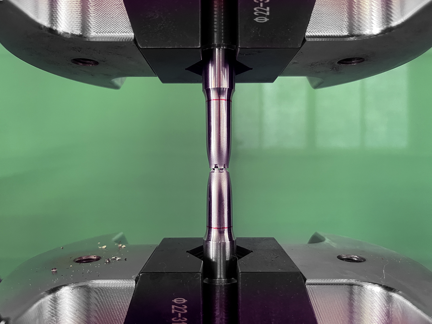
The machine follows a preset load rate, as defined by the operator in the control system. During this step, the UTM precisely increases the force on the sample at a controlled speed, providing accuracy in the measurement of how the material deforms or withstands stress. Sensors and load cells continuously measure the force applied, while extensometers or other measuring devices track any deformation in the material.
Step 3: Measuring the Response
As the UTM applies force to the specimen, the next critical step is accurately measuring the material's response. This involves two key components: the load cell, which measures the force being applied, and extensometers (or displacement transducers), which track how much the sample deforms under stress.
Data collected during this step is of utmost importance for understanding the material's properties. For instance, in a tensile test, the extensometer measures the specimen's elongation as the force increases. Meanwhile, the load cell continuously records the applied load. These measurements are displayed in real-time, allowing operators to observe key points such as the yield strength, ultimate tensile strength, and break point of the material.
Step 4: Analyzing and Recording the Data
After the UTM applies force and measures the sample’s response, the final step is analyzing and recording the collected data. This step is critical for understanding the material's mechanical properties, as it provides insights into how the material performs under stress. The UTM’s control system, usually equipped with advanced software, automatically compiles data points such as maximum load, deformation, yield strength, and elongation at break.
This data is then displayed as graphs, such as stress-strain curves, which visually represent the relationship between the applied force and the specimen's deformation. Operators can further analyze these graphs to extract specific material properties like the modulus of elasticity or breaking point. Once the analysis is complete, the results are saved in various formats (e.g., reports, PDFs, or spreadsheets) for documentation, review, or compliance purposes.

Looking for Reliable UTMs for Material Testing?
At TensileMill CNC, we understand the importance of reliable equipment for precise material testing. That’s why we offer high-tech universal testing machines designed to meet all your testing requirements, from tensile and compression tests to bending and shear evaluations. Our UTMs are built for accuracy, efficiency, and durability, making certain that your materials meet the highest standards.
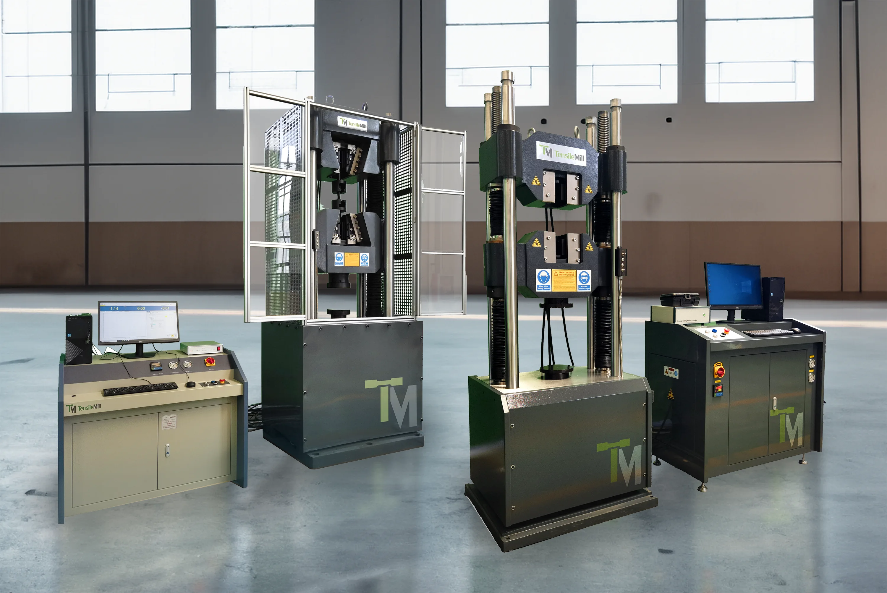
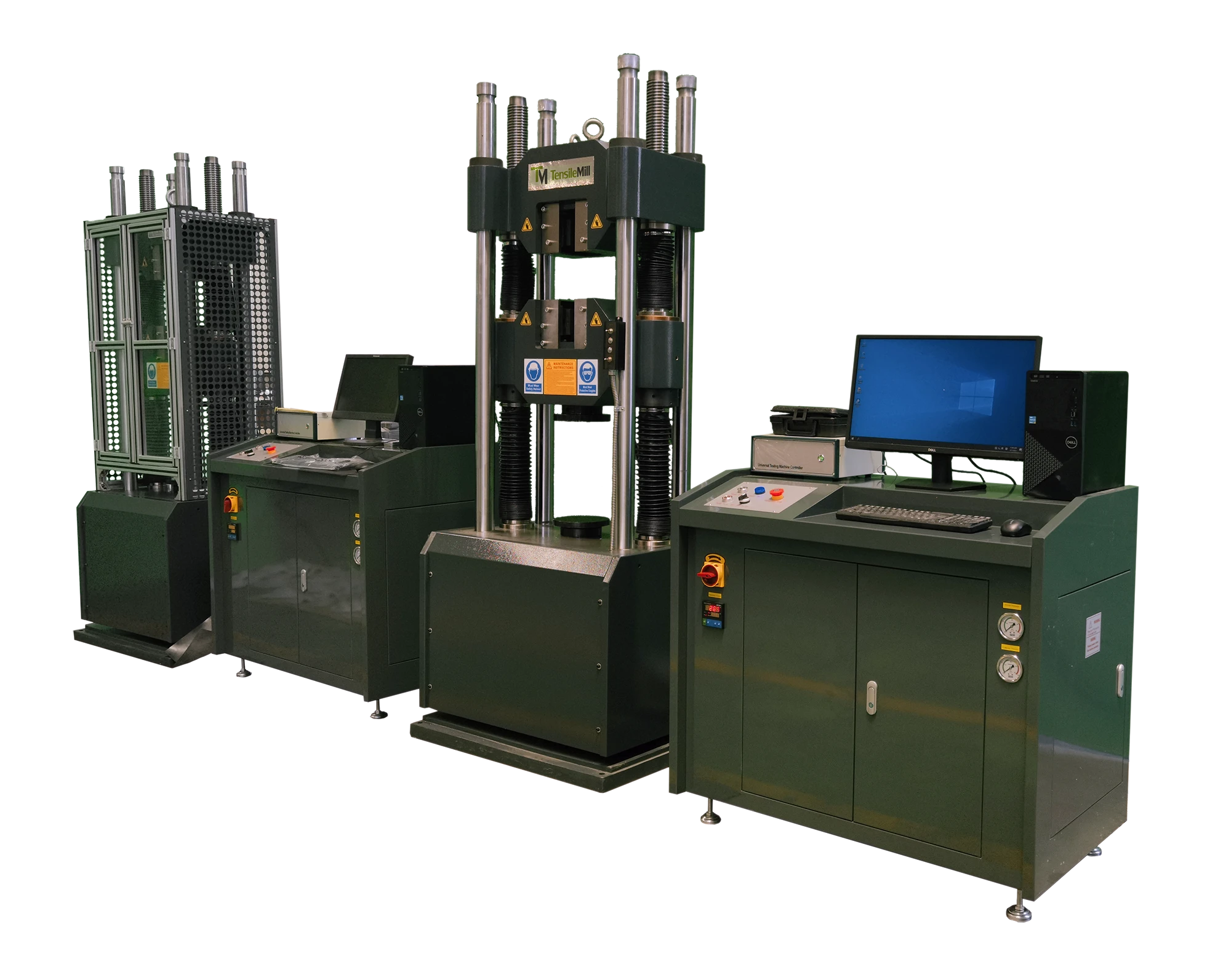
TM-EML - Dual-Column Floor-Standing Universal Testing System
The TM-EML - Dual-Column Floor-Standing Universal Testing System is a high-performance, versatile machine designed for precise material testing across a wide range of industries. Offering a force capacity ranging from 50kN to 600kN, it is ideal for testing metals, building components, large fasteners, composites, and wood products.
In ferrous alloys like steel, annealing typically involves heating the metal beyond its upper critical temperature, followed by slow cooling. This results in pearlite, a softer and more ductile microstructure. For non-ferrous metals, annealing removes hardness induced by cold working, making them easier to shape and machine. Different types of annealing, such as full annealing, process annealing, and recrystallization annealing, are used depending on the specific requirements of the metal and its intended application.
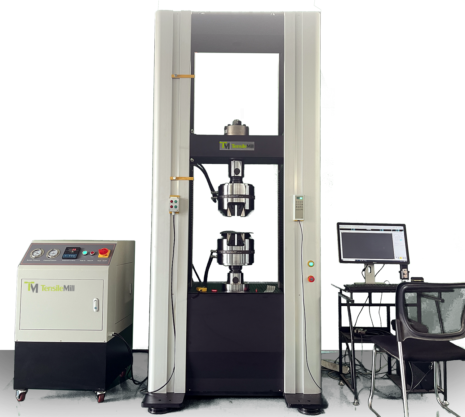
Key features of the TM-EML system include:
- High Accuracy: With a tolerance of ±0.5% of the reading, it provides exceptional precision during tensile, compression, bending, and shear tests.
- Electromechanical Drives: The system uses high-speed, low-vibration electromechanical drives, offering optimal performance with minimal vibration.
- Robust Load Frame: The dual-column design provides stability for large-scale and high-force testing.
- Pre-loaded Ball Screws: Provide maximum accuracy during testing, supported by linear motion guides for excellent alignment.
- Advanced Software: The system is compatible with a wide range of industry standards (ASTM, ISO, DIN, EN, and BS) and comes with comprehensive, user-friendly software for data analysis and control.
- Comprehensive Testing Capabilities: This system is equipped with a diverse selection of grips, fixtures, and extensometers, allowing for a variety of material testing applications.
With advanced control systems, including USB 2.0 communication for easy data exchange and real-time monitoring, the TM-EML system offers both high performance and reliability. It also includes safety features such as automatic limit checks for overload, temperature, and voltage parameters, making sure of long-term durability and accurate testing.
How UTMs Work and Why It Matters
Understanding how universal testing machines operate is crucial for anyone involved in material testing. UTMs function by applying controlled forces—whether tensile, compressive, or shear- to a test specimen to measure its response. This process, including the careful steps of sample preparation, force application, and real-time data measurement, enables precise analysis of material properties like tensile strength, elasticity, and yield points. The machine’s components, such as the actuator, load cell, and extensometer, all work together to provide a high degree of accuracy and repeatability.
If you have questions or would like more detailed information, please feel free to contact us directly or request a quote. All your equipment needs can be met by us!